U-Net. Couple of tricks for image segmentation.
Tags:
CV
|
segmentation
|
tricks
U-Net
Model used for semantic and instance segmentation, in the original article, model used for biomedical image segmentation task such as ISBI. Besides, in paper offered some tricks which can improve segmentation, such as augmentation, pixel weighting for loss function, etc.
Essence and architecture
Model consist on follow parts(like in FCN):
- Encoder, it needs to extract ‘WHAT’ info (more detail in [1] and in FCN) this information allows get features about object(cat/dog/backgroud/…) and answer questions about what on image, but as you increase the network level, positional data about WHERE this dog/cat/etc object is lost, at least because of size of the feature maps from encoder output (is less than the source image);
- Decoder, need to recover positional information (‘WHERE’) from feature maps on encoder output.
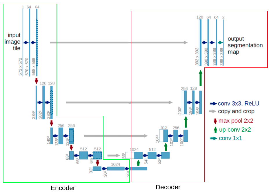
Figure A. U-Net architecture.
However, U-Net is different from FCN, following moments:
- Feature maps stacked in U-Net, instead sum it like in FCN;
- Convolution operation after fusion of feature maps;
- In skip connection (gray arrow “copy and crop” in figure A) feature maps crop and as a consequence, final segmentation belongs to only central part of input image(for example size of the input image is 572x572, binary masks is 388x388).
Architecture. By increasing the network level in encoder part number of feature maps(channels) doubles(in decoder inversely). In the decoder part, feature maps stack with cropped feature maps from the corresponding level of the network in encoder part, because feature maps from encoder contain more localization information. For getting in output segmentation maps, used 1x1 kernels of conv. layer.
Tricks
Image B. Overlap tile approach, used for segmentation high resolution or large images, yellow area in rectangle with segmentation, The blue area is all source image, consequently, cut image on patches, we may more accurately and seamlessly segmentation high resolution images. If the patch is located on the edge of the image, the missing part is replaced by a mirrored central(yellow area).
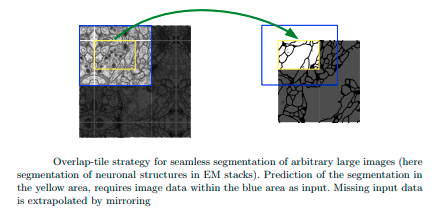
Figure B. Overlap tile
Image C. One of the techniques of image augmentation - elastic deformation.
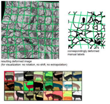
Figure C. Elastic deformation
In cases when objects may be nearly located and accidently segment as one object, there has been a proposed technique of increase loss function weights on pixels that border between these objects. The last right heat map image demonstrates it.
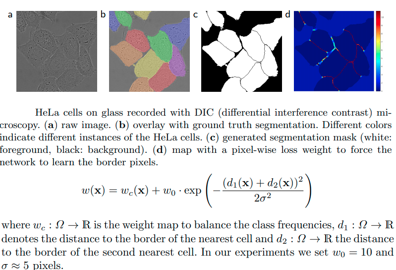
Figure D. Weight map.
Links